|
|
12 months ago | |
|---|---|---|
| 21.png | 1 year ago | |
| 22.png | 1 year ago | |
| 23.png | 1 year ago | |
| 24.png | 1 year ago | |
| 25.png | 1 year ago | |
| 26.png | 1 year ago | |
| 27.png | 1 year ago | |
| 28.jpg | 12 months ago | |
| README.md | 12 months ago | |
| pool_kit_modified.ino | 1 year ago | |
README.md
DESCRIPTION
This repository contains the pool_kit_modified.ino file, which was generated by modifying the source_code.ino file from the Original_Code_Pool_Kit repository. The purpose of these changes was mainly to add different sensors to the Wi-Fi Pool Kit and changing the format the data is shown in the Arduino Serial Monitor, specifically so that the text printed is only the numeric data of the parameters that are being measured, but these printed numeric data to be separated by commas so that it turns out easy for the user to copy the printed information into a .CSV file, since this is the most common format used for data analysis with the Python language tools we work with.
I2C address and device list
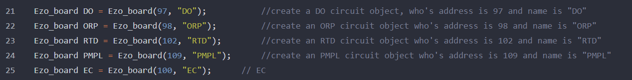
In the code lines 21 to 25, we have added instructions for the conductivity and dissolved oxygen circuits, including also the I2C addresses corresponding to each one of them. In this case, we have removed the instruction for the pH circuit since this parameter at the end was not considered as representative in the specific application that was being developed.
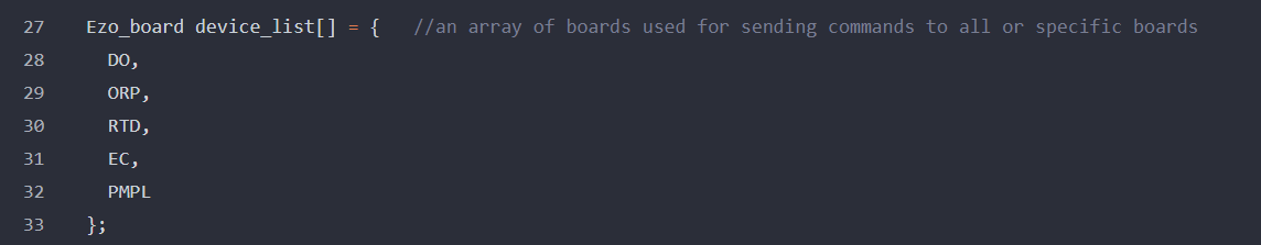
In the code lines 27 to 33, the names of the conductivity and dissolved oxygen circuits are added to the device list so that we can refer to them using their corresponding names.
Enable pins in the microcontroller
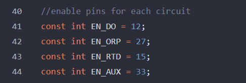
In the line 41 of the code, we need to set the pin number needed for our dissolved oxygen circuit, corresponding with the connection this circuit will have with the ESP32 microcontroller.
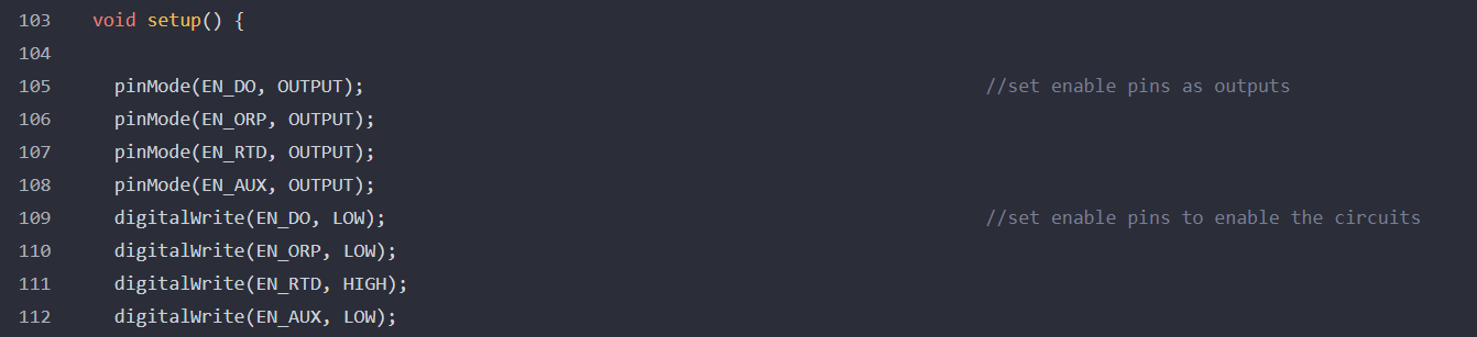
In the setup function, we also need to set up the pinMode for the added circuits, specifically if they need to have a LOW or HIGH digital value in the corresponding circuit.
The next image shows the connection for the circuits on the Atlas Scientific board.
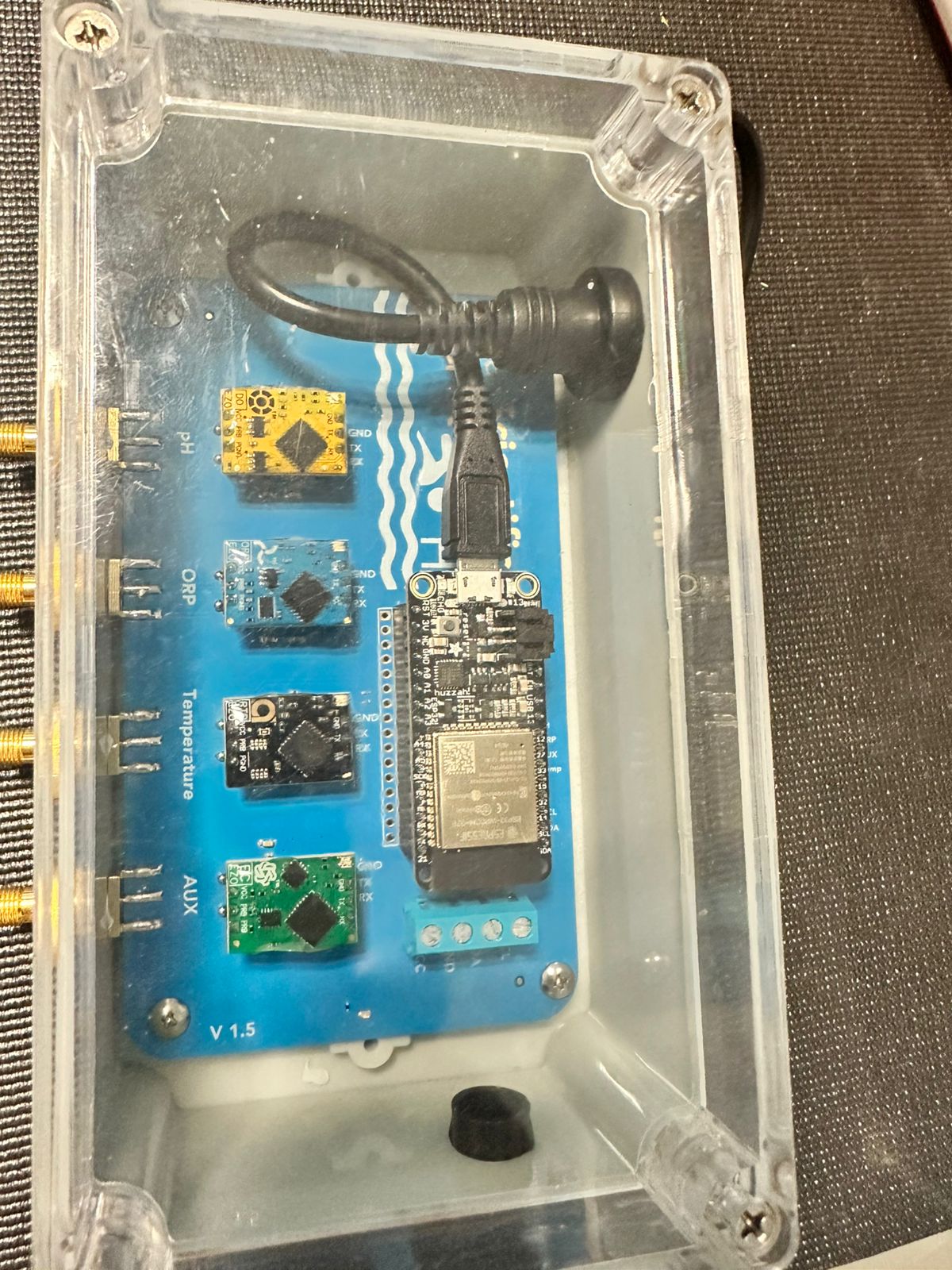
According with the image, from left to right, we have the yellow circuit for dissolved oxygen, then the blue circuit for ORP, the black circuit for temperature, and the green one goes for conductivity. Therefore, if it is neccessary replace a circuit for a different one, it is always important to remember that the first space on the board from left to right it is connected to pin 12 in the ESP32, the second space goes to pin 27, the third one has connection with pin 15, and the last one goes to pin 33. It means that no matter what circuit you are using on the Atlas Scientific board, you only need to specify on the code the correct pin for the connection with the ESP32 microcontroller.
step3 function
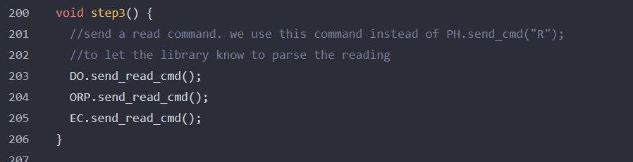
In the lines 200 to 206 from the pool_kit_modified.ino file, we modified this function by adding the next instructions:
DO.send_read_cmd(); EC.send_read_cmd();
These pair of instructions are commands defined in the libraries from Atlas Scientific imported to the Arduino IDE. In this part, as we are adding different sensors and circuits to our kit, we use these instructions to extract the readings of the measurements in the sensors, so that we can process those signals and show in the Serial Monitor the corresponding numeric data.
In this case for this function, we have removed the command for the pH variable since this parameters was not going to be used for data analysis.
Printing in the Serial Monitor
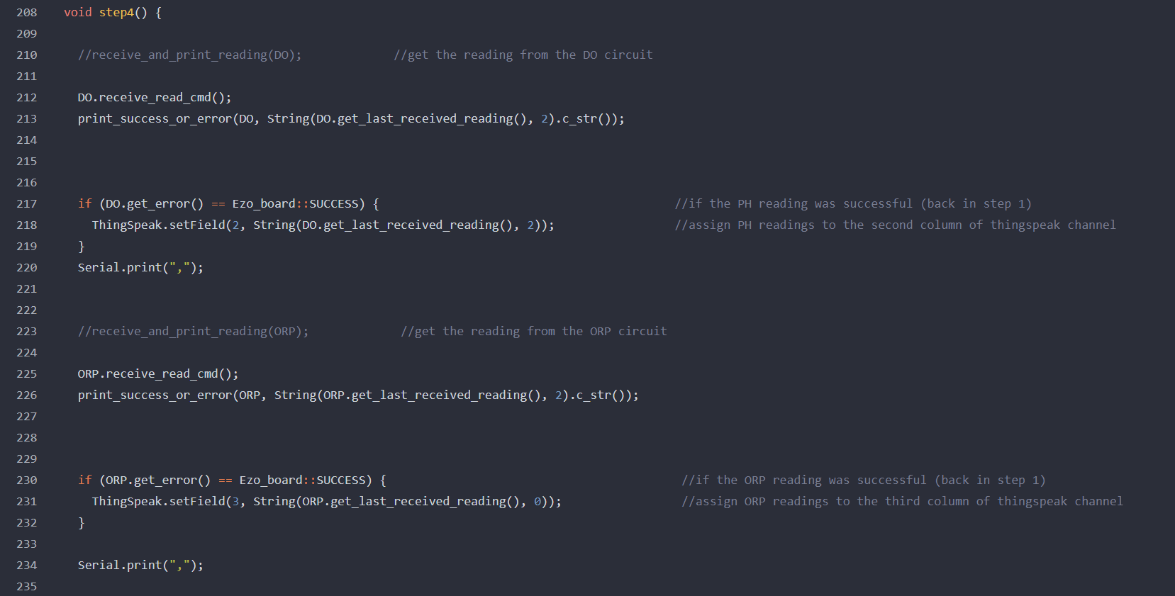
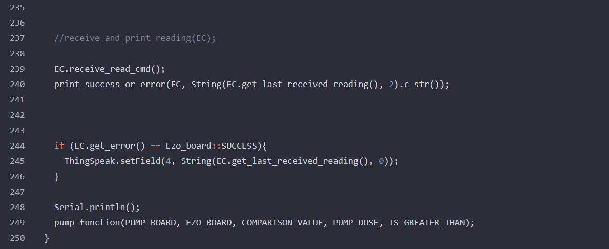
The last changes in the original source code were made in the step4 function.
All the data showed in the Serial Monitor consists on rows, and each of them has 4 numeric data in the next order: temperature, dissolved oxygen, ORP and conductivity. The changes made for this step4 function allow the user to print these 4 data one next to the other and separated by commas. This printing format was not available in the original source code downloaded from the Atlas Scientific website, but the changes are very useful, since the format now we have for the results in the Serial Monitor let us only copy the results printed into a .CSV file. And as we mentioned at the beginning, the .CSV file format makes it easier to import the data into a Python environment.